Sunday, August 14, 2011

VRRP with GNS3

Looking for practising VRRP with Packet tracer is impossible and I have tried with GNS3 as follow to understand more about VRRP.

Download completed lab file https://docs.google.com/viewer?a=v&pid=explorer&chrome=true&srcid=0B889ogd4ltI2YTcxODhkMzktNWRmYS00M2JlLTg2ZjQtYmVmODExNjI2MzRh&hl=en_US

If you want to know more about VRRP for CCNP switching exam, follow the post. Here is lab diagram.


R1 will be master and R2 will act as backup VRRP. MD5 authenication setup using key-string "test" and R1 will track preconfigured loopback lo0 with priority 200. When loopback lo0 down, it will decrease the value to 101 and configured value will be 99 left. Then, R2 will be acting as Master.

R3 will be working as PC and trying to achieve the testing by ping R4's loopback IP (4.4.4.4).

R1, R2 , R4 will be configure as 172.16.1.0/24, 172.16.2.0/24 networks and configure EIGRP for routing. Configure routing for all network including loopback using "network 0.0.0.0"

Configure R1 and R2 as follow.

In R1,

 vrrp 1 ip 192.168.1.10
 vrrp 1 priority 200
 vrrp 1 authentication md5 key-string test
 vrrp 1 track 1 decrement 101


In R2,
 vrrp 1 ip 192.168.1.10
 vrrp 1 authentication md5 key-string test

-----------------------------------------

In  R3, configure as PC follow;

interface FastEthernet0/0
ip address 192.168.1.3 255.255.255.0

In global config mode,  add two extra line for default gateway to VRRP IP and turn off ip routing as follow.

no ip routing
ip default-gateway 192.168.1.10

----------------------------------------
After all configured, check in R1's configuration using "sh vrrp" command and confirmed that R1 is Master.
Important note is that in VRRP, "preemption" is already enabled. So, the coup process is already enabled and no manually configuration is needed like in HSRP and GLBP.

R1#sh vrrp
FastEthernet0/0 - Group 1
  State is Master
  Virtual IP address is 192.168.1.10
  Virtual MAC address is 0000.5e00.0101
  Advertisement interval is 1.000 sec
  Preemption enabled
  Priority is 200
    Track object 1 state Up decrement 101
  Authentication MD5, key-string "test"
  Master Router is 192.168.1.1 (local), priority is 200
  Master Advertisement interval is 1.000 sec
  Master Down interval is 3.218 sec
-----------------
In R2,

R2#sh vrrp
FastEthernet0/0 - Group 1
  State is Backup
  Virtual IP address is 192.168.1.10
  Virtual MAC address is 0000.5e00.0101
  Advertisement interval is 1.000 sec
  Preemption enabled
  Priority is 100
  Authentication MD5, key-string "test"
  Master Router is 192.168.1.1, priority is 200
  Master Advertisement interval is 1.000 sec
  Master Down interval is 3.609 sec (expires in 2.657 sec)
-----------------------
Let's check in R1's log using "debug vrrp packets". Checking logs are important as you need to interpret the status of VRRP in exam. As you see that, Master VRRP is doing only advertising. 

R1#
*Mar  1 01:12:09.079: VRRP: Grp 1 sending Advertisement checksum C4E2
*Mar  1 01:12:10.075: VRRP: Grp 1 sending Advertisement checksum C4E2
R1#
*Mar  1 01:12:10.887: VRRP: Grp 1 sending Advertisement checksum C4E2
*Mar  1 01:12:11.739: VRRP: Grp 1 sending Advertisement checksum C4E2

Let's check in R2's log. R2 's backup VRRP and it's getting advertisement from R1's with priority 200

R2#
*Mar  1 01:17:09.039: VRRP: Grp 1 Advertisement priority 200, ipaddr 192.168.1.1
*Mar  1 01:17:09.039: VRRP: Grp 1 Event - Advert higher or equal priority
*Mar  1 01:17:09.987: VRRP: Grp 1 Advertisement priority 200, ipaddr 192.168.1.1
*Mar  1 01:17:09.987: VRRP: Grp 1 Event - Advert higher or equal priority
-----------------------
OK, now let's do traceroute from PC (R3) to R4's loopback 4.4.4.4. Route will use R1 to reach to 4.4.4.4

PC#traceroute 4.4.4.4

Type escape sequence to abort.
Tracing the route to 4.4.4.4

  1 192.168.1.1 132 msec 60 msec 16 msec
  2 172.16.1.4 88 msec *  140 msec

Check which MAC address is using for 192.168.1.10 in PC. It's using 0000.5e00.0101.

PC#sh arp
Protocol  Address          Age (min)  Hardware Addr   Type   Interface
Internet  192.168.1.2            51   c201.0ff0.0000  ARPA   FastEthernet0/0
Internet  192.168.1.3             -   c202.0ff0.0000  ARPA   FastEthernet0/0
Internet  192.168.1.10            4   0000.5e00.0101  ARPA   FastEthernet0/0
----------------
Clear arp cache in PC and let's change the status of R1's loopback to lower down the priority of R1 to 99.
Before to do that, it's need to create track object in R1. Interface tracking in VRRP is different with HSRP and GLBP. In GLBP and HSRP, you have to configure in interface mode.

Actually, there is no direct interface tracking system in VRRP to allow more capable routers as master role.

In global config mode, configure as follow in R1.

track 1 interface Loopback0 line-protocol

Make sure to include "track 1" in vrrp config in Interface fa0/1 as follow.
vrrp 1 track 1 decrement 101
--------------------------------
Ok, let's shutdown loopback 0 from R1.

R1(config-if)#
*Mar  1 01:25:10.631: %TRACKING-5-STATE: 1 interface Lo0 line-protocol Up->Down
---------------------
R1(config-if)#
*Mar  1 01:25:14.079: %VRRP-6-STATECHANGE: Fa0/0 Grp 1 state Master -> Backup
------------------------------
In R2, you will notice the following console message appear that it's change to Master VRRP

R2#
*Mar  1 01:25:10.055: %VRRP-6-STATECHANGE: Fa0/0 Grp 1 state Backup -> Master
--------------------------------
Let's check traceroute again from PC to 4.4.4.4. As you seen in below, this time, PC is using R2 as next hop to reach R4.

PC#traceroute 4.4.4.4

Type escape sequence to abort.
Tracing the route to 4.4.4.4

  1 192.168.1.2 64 msec 36 msec 12 msec
  2 172.16.2.4 36 msec *  116 msec
-------------------------------------
Interesting , checking MAC address of 192.168.1.10 in PC is the same as before as VRRP is using the same IP with same MAC address (0000.5e00.0101) for master and backup where ((0000.5e00.01) is for VRRP's address and (01) is for VRRP group number.

PC#sh arp
Protocol  Address          Age (min)  Hardware Addr   Type   Interface
Internet  192.168.1.2             1   c201.0ff0.0000  ARPA   FastEthernet0/0
Internet  192.168.1.3             -   c202.0ff0.0000  ARPA   FastEthernet0/0
Internet  192.168.1.10            1   0000.5e00.0101  ARPA   FastEthernet0/0

Friday, August 12, 2011

VOIP Lab with Packet Tracer 5.3

I have looked in Internet as usual using Google :) to test VOIP using Packet Tracer. Two or three links fond and all are interesting. But, I would like to customize my own and see below if you are also looking like me.

Here is lab diagram. Download completed Packet Tracer file from https://docs.google.com/leaf?id=0B889ogd4ltI2MTFmYzJhNjgtYjE3OC00ZmE5LWEzZWMtOGFiOTg0MDkwMmM1&hl=en_US


It's a simple lab. One Cisco router as "Configure Call Manager ExpressTM", Cisco phones, digital to analog home VOIP PT to convert from digital to analog phone. I have added two PCs using different VLAN; one is connected with Cisco IP phone to test mls. VLAN 1 is for voice VLAN and two PCs are in VLAN 10 with static IP.

First, drag all devices in Cisco Packet Tracer and configure router to work as DHCP server to lease IP addresses for IP phones.

ip dhcp pool test-vlan
 network 192.168.10.0 255.255.255.0
 default-router 192.168.10.1
 option 150 ip 192.168.10.1

Using option 150 is required to provide IP address to Cisco phone. Pool range is the whole network of 192.168.10.0/24.

More detail about how to configure for IP phones are avaliable in packet tracer website at http://www.packettracernetwork.com/voipconfiguration.html

Here is the config file of router.

telephony-service
 max-ephones 3
 max-dn 3
 ip source-address 192.168.10.1 port 2005
 auto assign 1 to 5
!
ephone-dn 1
 number 1001
!
ephone-dn 2
 number 1005
!
ephone-dn 3
 number 1010
!

I have used IP phones with power supply. So, power adapter need to plug to get IP phone online. If you don't want and need PoE, have to use multilayer switch.

Configure switch as follow; Enable trust boundary to Cisco phone using "mls qos trust device cisco-phone".

interface FastEthernet0/1
 switchport access vlan 10
 switchport mode trunk
 switchport voice vlan 1
 mls qos trust device cisco-phone
!
interface FastEthernet0/4
 switchport mode access
 switchport voice vlan 1
!
interface FastEthernet0/5
 switchport mode access
 switchport voice vlan 1


Check in switch after phone online whether it's trusted Cisco Phone or not by executing command "mls qos interface fa0/1". trust device: cisco-phone is appear in outpout.


Switch#sh mls qos interface fa0/1
FastEthernet0/1
trust state: not trusted
trusted mode: not trusted
COS override: dis
default COS: 0
pass-through: none
trust device: cisco-phone


As soon as IP phones are online, following message appear in Cisco router and confirmed that phone are registered with IP address.


Router#
%IPPHONE-6-REGISTER: ephone-1 IP:192.168.10.2 Socket:2 DeviceType:Phone has registered.
Router#
%IPPHONE-6-REGISTER: ephone-2 IP:192.168.10.3 Socket:2 DeviceType:Phone has registered.


Phone number will be appear in upper right corner of the phone GUI screen.


Check lease IP address in router using following command.

Router#sh ip dhcp binding 
IP address       Client-ID/              Lease expiration        Type
                 Hardware address
192.168.10.3     0006.2A21.B937           --                     Automatic
192.168.10.4     000B.BE52.8501           --                     Automatic
192.168.10.2     0001.9628.4786           --                     Automatic
192.168.10.6     0010.11E9.75C9           --                     Automatic


For HomeVOIP-PT device, type the Cisco router (Call Manager) ip address as follow;


Check by moving mouse over to phone device whether it's getting IP address and appearing extension number or not as follow.


Try to make call between two IP phones as well as from analog to IP phone.

Configure different IP address for two PCs as mentioned in lab diagram; 192.168.1.1 and 192.168.1.2 and assign to VLAN 10. Voice VLAN has already configured as VLAN 1.


Friday, April 22, 2011

IPv6 - 6to4 Tunnels using IPv4 EIGRP routes


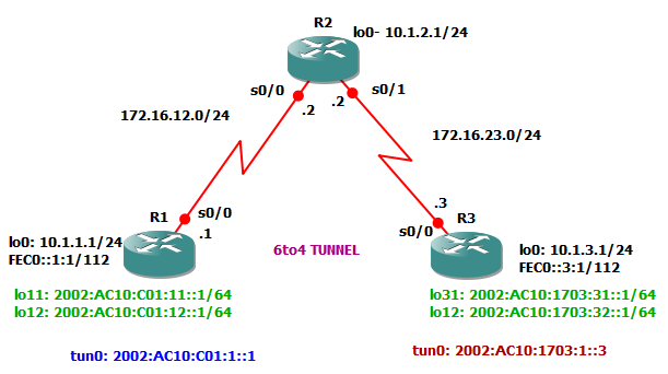
In this lab, configure all routers with IPV6 and IPV4 addresses and establish communication between R1 and R3 using IPv6to4 tunnelling.

Objectives are as follows;
(1) Configure EIGRP for IPV4.
(2) Create a 6to4 tunneling
(3) Configure static IPv6 routes.


In R1, configure the following configurations for tunnelling.

interface Tunnel0
 no ip address
 no ip redirects
 ipv6 address 2002:AC10:C01:1::1/64
 tunnel source Serial0/0
 tunnel mode ipv6ip 6to4


For IPv6 routing,

ipv6 unicast-routing
ipv6 route 2002::/16 Tunnel0
ipv6 route FEC0::3:0/112 2002:AC10:1703:1::3

Enabling simple EIGRP routing for IPv4 networks are as follow;

router eigrp 1
 network 10.0.0.0
 network 172.16.0.0
 no auto-summary
-------------
Result of routing in R1 are as follow;

R1#sh ipv6 route
IPv6 Routing Table - 12 entries
Codes: C - Connected, L - Local, S - Static, R - RIP, B - BGP
       U - Per-user Static route
       I1 - ISIS L1, I2 - ISIS L2, IA - ISIS interarea, IS - ISIS summary
       O - OSPF intra, OI - OSPF inter, OE1 - OSPF ext 1, OE2 - OSPF ext 2
       ON1 - OSPF NSSA ext 1, ON2 - OSPF NSSA ext 2
S   2002::/16 [1/0]
     via ::, Tunnel0
C   2002:AC10:C01:1::/64 [0/0]
     via ::, Tunnel0
L   2002:AC10:C01:1::1/128 [0/0]
     via ::, Tunnel0
C   2002:AC10:C01:11::/64 [0/0]
     via ::, Loopback11
L   2002:AC10:C01:11::1/128 [0/0]
     via ::, Loopback11
C   2002:AC10:C01:12::/64 [0/0]
     via ::, Loopback12
L   2002:AC10:C01:12::1/128 [0/0]
     via ::, Loopback12
L   FE80::/10 [0/0]
     via ::, Null0
C   FEC0::1:0/112 [0/0]
     via ::, Loopback0
L   FEC0::1:1/128 [0/0]
     via ::, Loopback0
S   FEC0::3:0/112 [1/0]
     via 2002:AC10:1703:1::3
L   FF00::/8 [0/0]
     via ::, Null0


-------------------------------------------
R1's IPV6 addressing are as follows;

R1#sh ipv6 int brief
Serial0/0                  [up/up]
Serial0/1                  [administratively down/down]
Serial0/2                  [administratively down/down]
Serial0/3                  [administratively down/down]
Loopback0                  [up/up]
    FE80::9CD7:2EFF:FEF0:99FA
    FEC0::1:1
Loopback9                  [up/up]
Loopback11                 [up/up]
    FE80::9CD7:2EFF:FEF0:99FA
    2002:AC10:C01:11::1
Loopback12                 [up/up]
    FE80::9CD7:2EFF:FEF0:99FA
    2002:AC10:C01:12::1
Tunnel0                    [up/up]
    FE80::AC10:C01
    2002:AC10:C01:1::1
----------------------------------------------------------------------------
In R3, 

Enabling for tunnelling are as follows;

ipv6 unicast-routing
 ipv6 address FEC0::3:1/112
 ipv6 address 2002:AC10:1703:31::1/64
 ipv6 address 2002:AC10:1703:32::1/64
 ipv6 address 2002:AC10:1703:1::3/64
 tunnel mode ipv6ip 6to4
ipv6 route 2002::/16 Tunnel0
ipv6 route FEC0::1:0/112 2002:AC10:C01:1::1
------------

IPV6 addressing in R3 are as follows;

R3#sh ipv6 int brief
Serial0/0                  [up/up]
Serial0/1                  [administratively down/down]
Serial0/2                  [administratively down/down]
Serial0/3                  [administratively down/down]
Loopback0                  [up/up]
    FE80::9CD7:2EFF:FEF0:99FA
    FEC0::3:1
Loopback31                 [up/up]
    FE80::9CD7:2EFF:FEF0:99FA
    2002:AC10:1703:31::1
Loopback32                 [up/up]
    FE80::9CD7:2EFF:FEF0:99FA
    2002:AC10:1703:32::1
Tunnel0                    [up/up]
    FE80::AC10:1703
    2002:AC10:1703:1::3

-------------------
IPV6 routing table is as follows;

R3#sh ipv6 route
IPv6 Routing Table - 12 entries
Codes: C - Connected, L - Local, S - Static, R - RIP, B - BGP
       U - Per-user Static route
       I1 - ISIS L1, I2 - ISIS L2, IA - ISIS interarea, IS - ISIS summary
       O - OSPF intra, OI - OSPF inter, OE1 - OSPF ext 1, OE2 - OSPF ext 2
       ON1 - OSPF NSSA ext 1, ON2 - OSPF NSSA ext 2
S   2002::/16 [1/0]
     via ::, Tunnel0
C   2002:AC10:1703:1::/64 [0/0]
     via ::, Tunnel0
L   2002:AC10:1703:1::3/128 [0/0]
     via ::, Tunnel0
C   2002:AC10:1703:31::/64 [0/0]
     via ::, Loopback31
L   2002:AC10:1703:31::1/128 [0/0]
     via ::, Loopback31
C   2002:AC10:1703:32::/64 [0/0]
     via ::, Loopback32
L   2002:AC10:1703:32::1/128 [0/0]
     via ::, Loopback32
L   FE80::/10 [0/0]
     via ::, Null0
S   FEC0::1:0/112 [1/0]
     via 2002:AC10:C01:1::1
C   FEC0::3:0/112 [0/0]
     via ::, Loopback0
L   FEC0::3:1/128 [0/0]
     via ::, Loopback0
L   FF00::/8 [0/0]
     via ::, Null0
--------------------------
Enabling IPv4 EIGRP routing as follows;

router eigrp 1
 network 10.0.0.0
 network 172.16.0.0
 no auto-summary

Virtualization with CentOS and VirtualBox in Window 7

It's difficult to test "Virtualization" if you don't have powerful server.
But, you can test "Virtualization" using Sun Virtual Box.

It means installation CentOS Linux server guest OS inside CentOS virtual machine using VirtualBox.

In short, it's nesting virtual machines using Xen in Virtual Box.  Well, as usual go, browse and search in Internet. Most are not recommend and I'm really interested to test.

The purpose of installation is how CentOS virtualization works with Xen and it's not for production.

So, read on below if you are on the same boat as me.

I am using CentOS 5.5 and install it in Sun VirtualBox. I think this will be easy for you as well. Just download DVD ISO file from www.centos.org using from direct link or torrent.
  • After all CentOS is up and running in VirtualBox, type to following command to install Xen kernel.
  • yum install kernel-xen xen
  • Make sure that "VT-x/AMD-V, Nested Paging, PAE/NX is enabled in virtual machine as in below picture.


  • After successfully installation of Xen kernel, system need to reboot. On reboot, press Enter key when there is boot menu pops up and select "Xen Kernel"
  • To permanently start Xen kernel when system boots up, edit the grub.conf file and select the new kernel in first place.
  • There are two types of virtualization as follows;
  • Full-virtualization: hardware is emulated to the extent that unmodified guest operating systems can run on the virtualization platform. Normally, this means that various hardware devices are emulated.
  • Paravirtualization: in paravirtualization the guest operating system is ported to the hypervisor, a layer sitting between the hardware and virtualized systems. Because this normally doesn't require full device emulation or dynamic recompiling to catch privileged instructions, paravirtualization often performs at a near-native speed.
  • As the lab that I'm going to is going to use Virtual machine, this lab is for "paravirtualization".
  • After installation Xen and upgrade kernel, it's ready to create Xen domain.
  • Create a new Xen guest as follow;
  • virt-install --paravirt --name cent01 --ram 256 --file /vm/cent01.img --file-size 10 --nographic --localtion http://192.168.0.55/pub
  • Before you execute previous command, you have to mount the CentOS image and create as public directory.
  • The reasons is you can't mount virutal machine CD Drive as you are using Virtual Machine and not real hardware.
  • To mount CentOS image as to appear in website, execute the following command
  • mount -o loop /CentOS.iso /var/www/html/pub
  • Make sure to install Apache in your Virutal Machine first and create pub directory.
  • Finally, Xen guest will create and start installation.
  • After complete installation, you can clone the Xen guest as follow.
  • virt-clone --original cent01 --name clonecent01 --file /vm/clonecent01.img
For more information about CentOS virtualization, go and browse at http://www.centos.org/docs/5/html/Virtualization-en-US/

Implementing routing for branch offices and mobile workers

The following labs included the followings to practice all in one.

(1) Configure NAT
(2) Configure IP Sec VPN
(3) Configure GRE tunnel over IPSec
(4) Enabled dynamic routing over a GRE tunnel

Lab topology is as shown in below.


Your organization is expanding it's operation and wants to connect a branch site. To avoid expensive WAN costs, the decision make to use Internet as WAN link. So, you suggest to use IPSec VPN to support all traffic going between two sites. In addition, to have dynamic routing between two sites, implementing Generic Routing Encapsulation (GRE).

For branch office to connect to Internet, lab needs to use NAT from branch office.

If you are interested to practice, download the completed GNS3 lab files from here https://docs.google.com/leaf?id=0B889ogd4ltI2MzBjZmFiMGQtM2NhYi00NmI2LTk5YTktODM3MmNjMDQ5ZjBk&hl=en&authkey=CLH3uNoC


Tuesday, April 12, 2011

Deploying unattendent Firefox 4.0 to all PCs in LAN

For those who would like to deploy Firefox 4.0 (new release) to all network PCs, download http://www.mozilla.com/en-US/firefox/fx/

Extract Firefox 4.0.exe file into folder using 7Zip


After extraction into folder from the EXE file, create batch file as follows;


@echo ***** Installation Firefox 4.0 now ***
@echo off
setup.exe --ms

Script will install Firefox 4.0 silently and update the existing version if necessary. Script can install if even the user opening old Firefox browser. But, update will work after closing current Firefox browser and open


Create network share and place installer file and batch file. Deploy as you wish from remote using Group Policy or using "psexec.exe" if you are not in Domain environment.


Command.com MS DOS black window will display during installation.

If you want to hide MSDOS black window, download "Hidden Start" program from http://www.ntwind.com/software/utilities/hstart.html


After deploying the script, check the add-ons from old firefox and update as necessary. If you can't find updated Add-ons, disable it.

Deploying unattendent installation of Java 6 update 24

For those who would like to deploy latest Java update to all network PC, download latest Java 6 update 24 from http://www.java.com/en/download/manual.jsp


After downading the EXE file, create batch file as follows;


@echo *** Installation Java 6 update 24 ****
@echo off
jre-6u24-windows-i586-s.exe /s /v "/qn IEXPLORER=1 MOZILLA=1 JAVAUPDATE=0 JU=0 REBOOT=Suppress"


Script will install Java sliently and update in "IE" and "Firefox" and automatic update will turn off. If reboot, requires, it won't reboot automatically.


Create network share and place installer file and batch file.

Deploy as you wish from remote using Group Policy or using "psexec.exe" if you are not in Domain environment.


Command.com MS DOS black window will display during installation.

If you want to hide MSDOS black window, download "Hidden Start" program from http://www.ntwind.com/software/utilities/hstart.html


After deploying the script, check whether it has install successfully by browsing to http://www.java.com/en/download/installed.jsp and click "Verify Java Version"